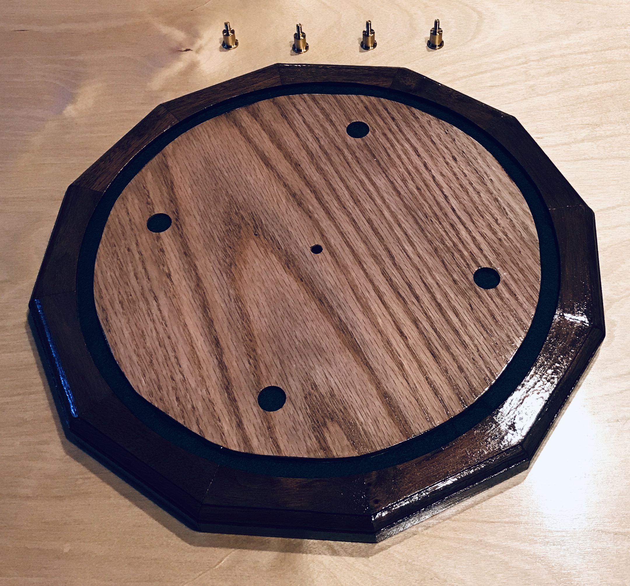
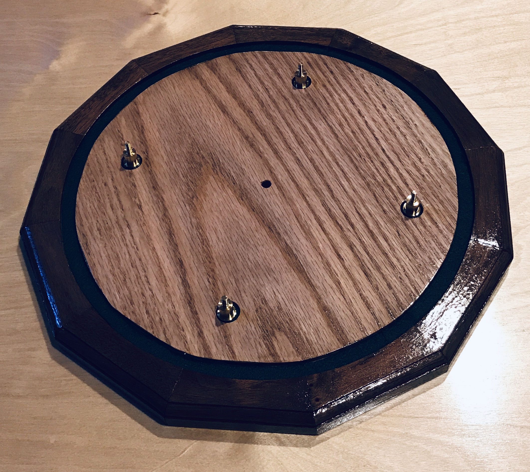
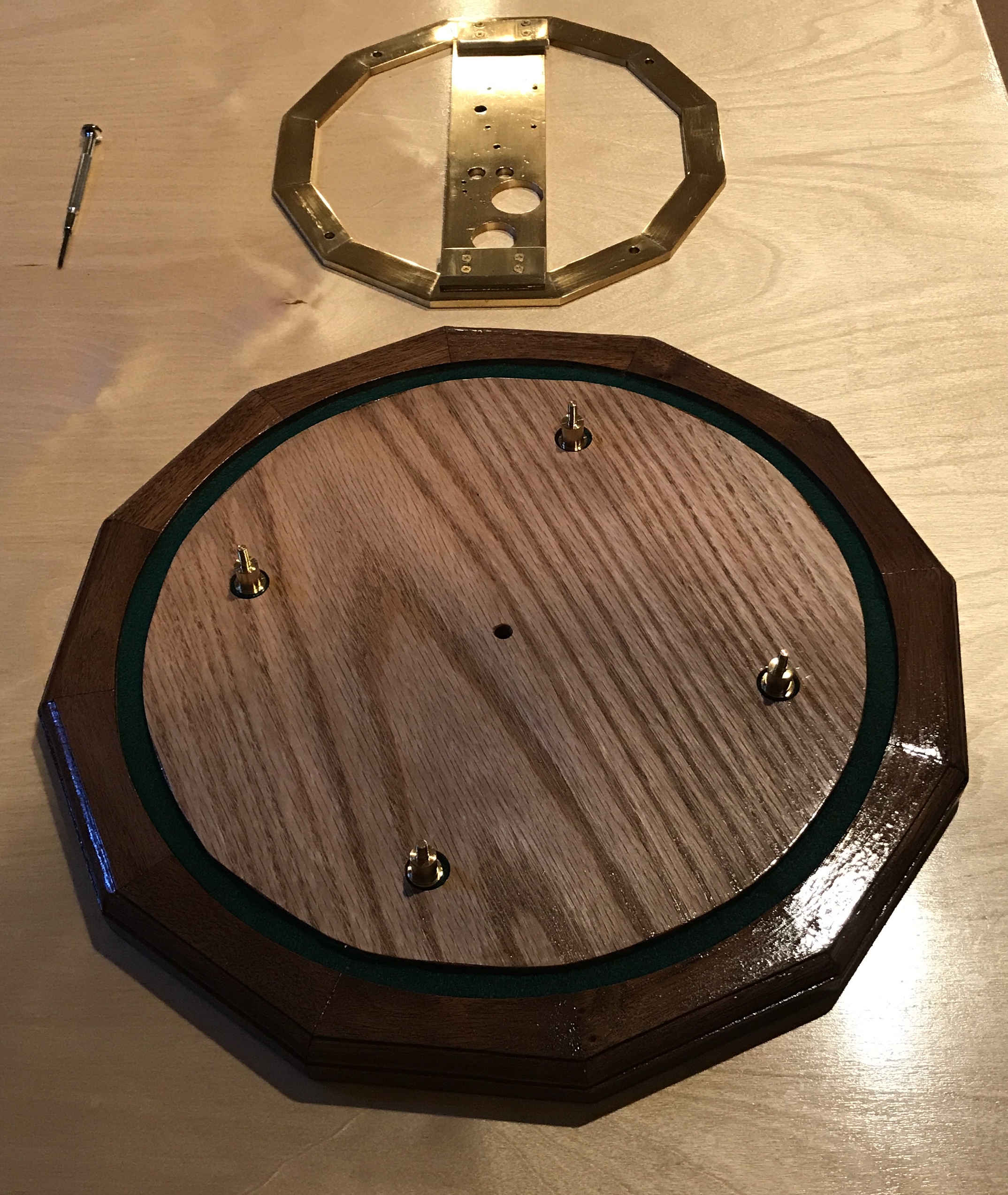
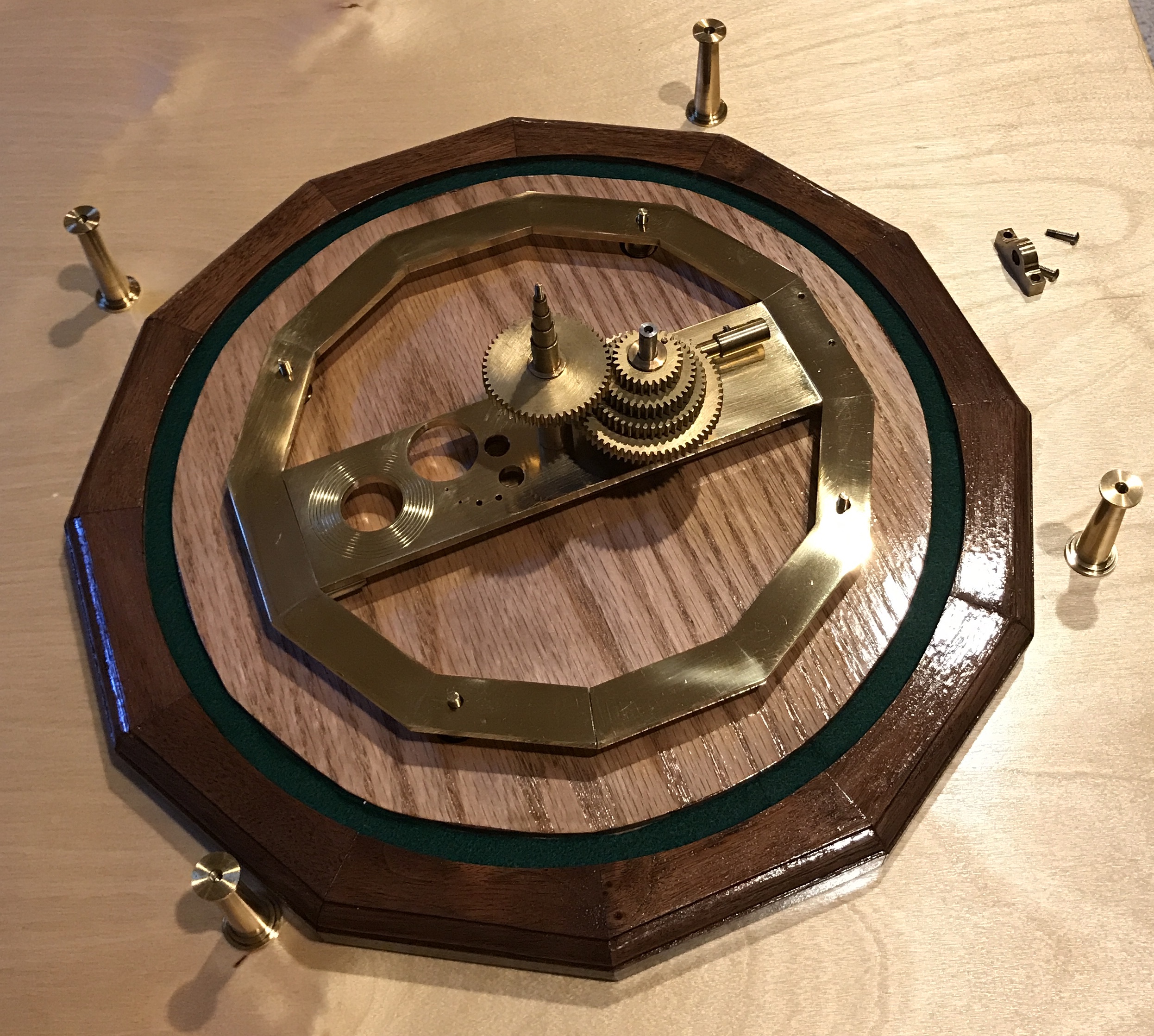
Decided to assemble the orrery today. I have never seen it put together after polishing the various parts. As it was assembled I discovered that at least six screws are missing. The assembly was documented with many photos. I did the assembly on top of the footstool desk. The camera was "mounted" on the magnifier/part holder, which sat on top of the machinist's tool chest. The lighting was not ideal. At least two photos accompany each step. The first is the assembly up to that point accompanied by the next set of parts. The second is this set of parts added to the assembly. All of the parts except for the screws were made in my shop. First the feet were placed in the base. These also serve as screws to attach to the columns seen later.
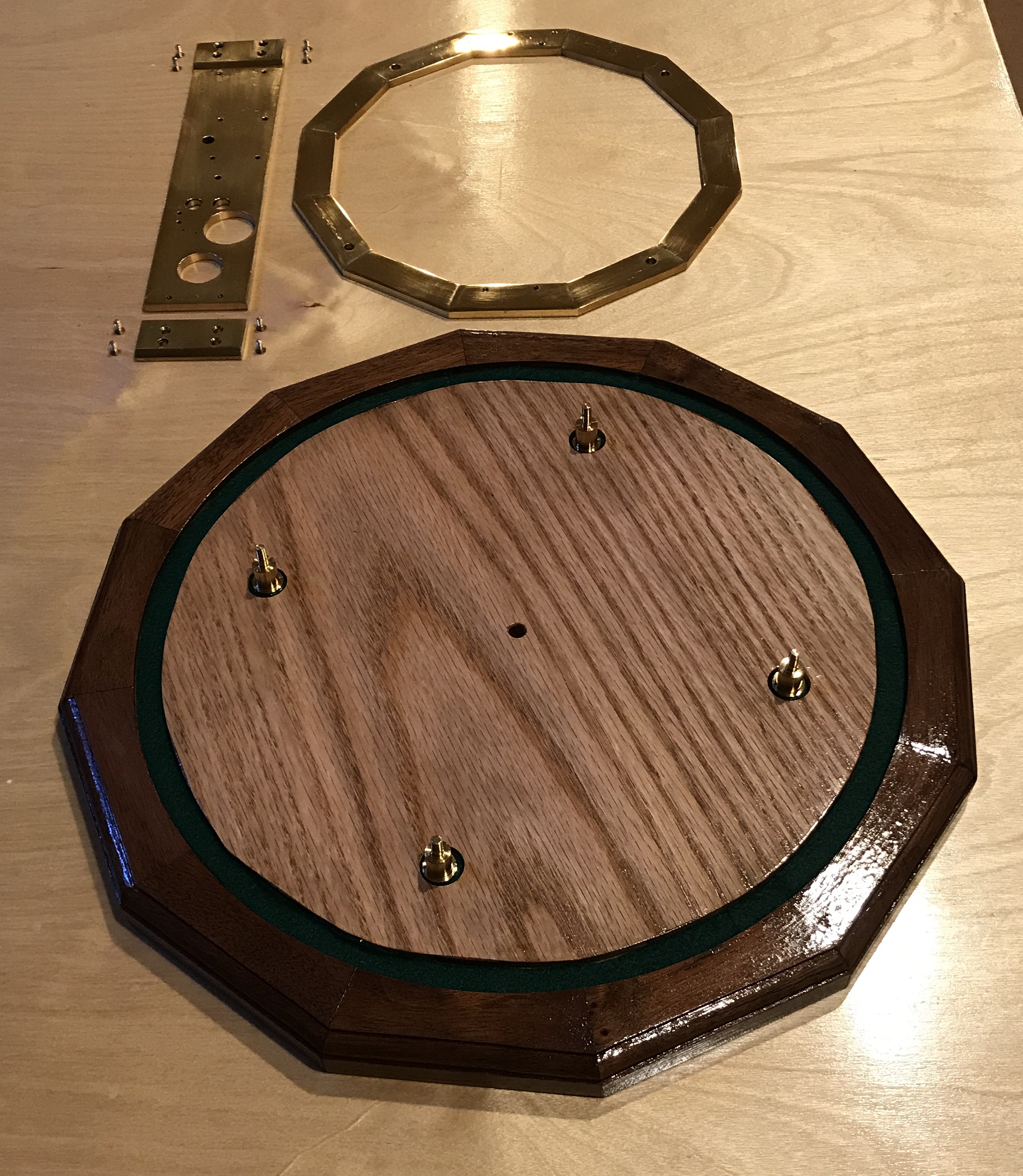
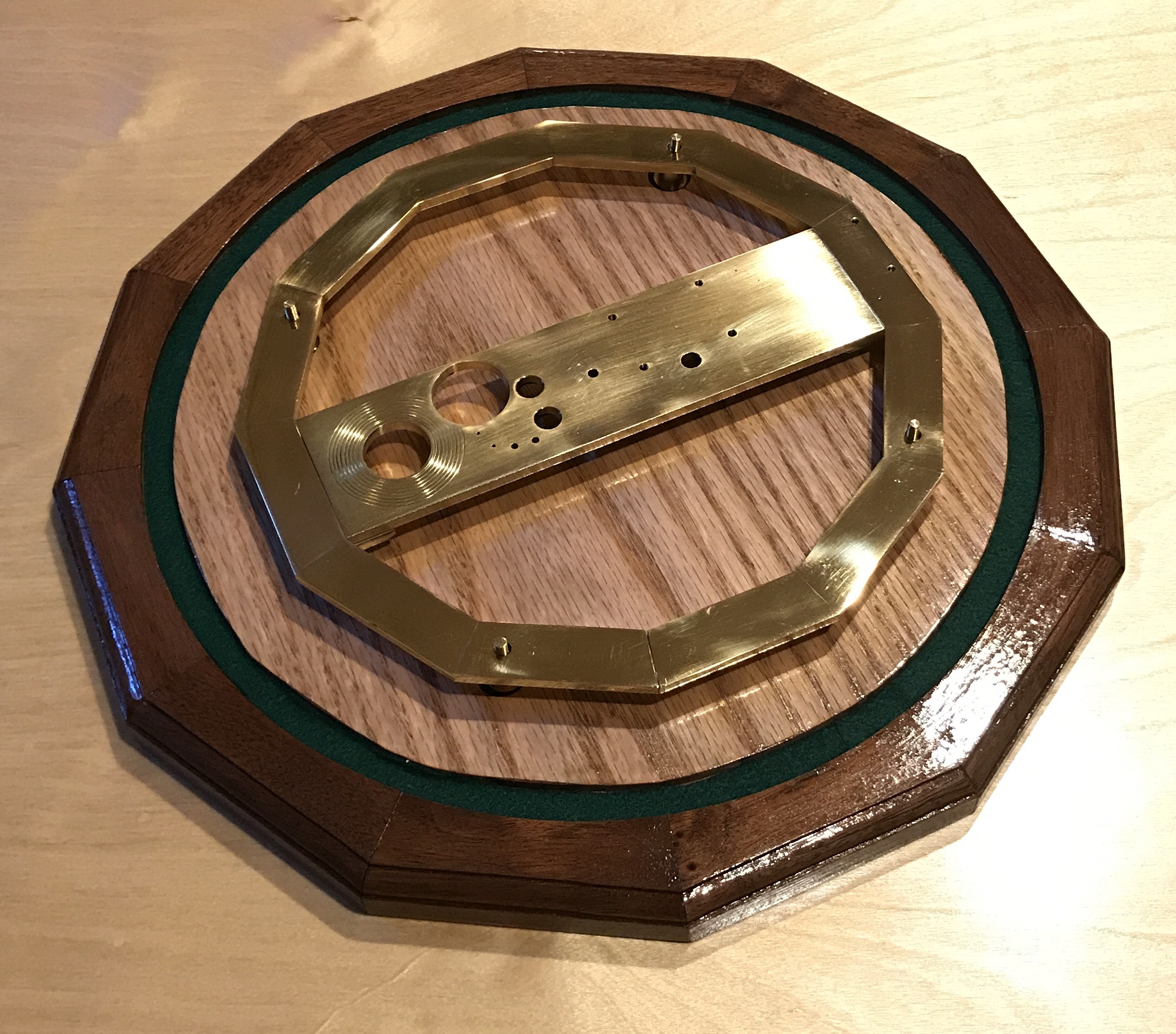
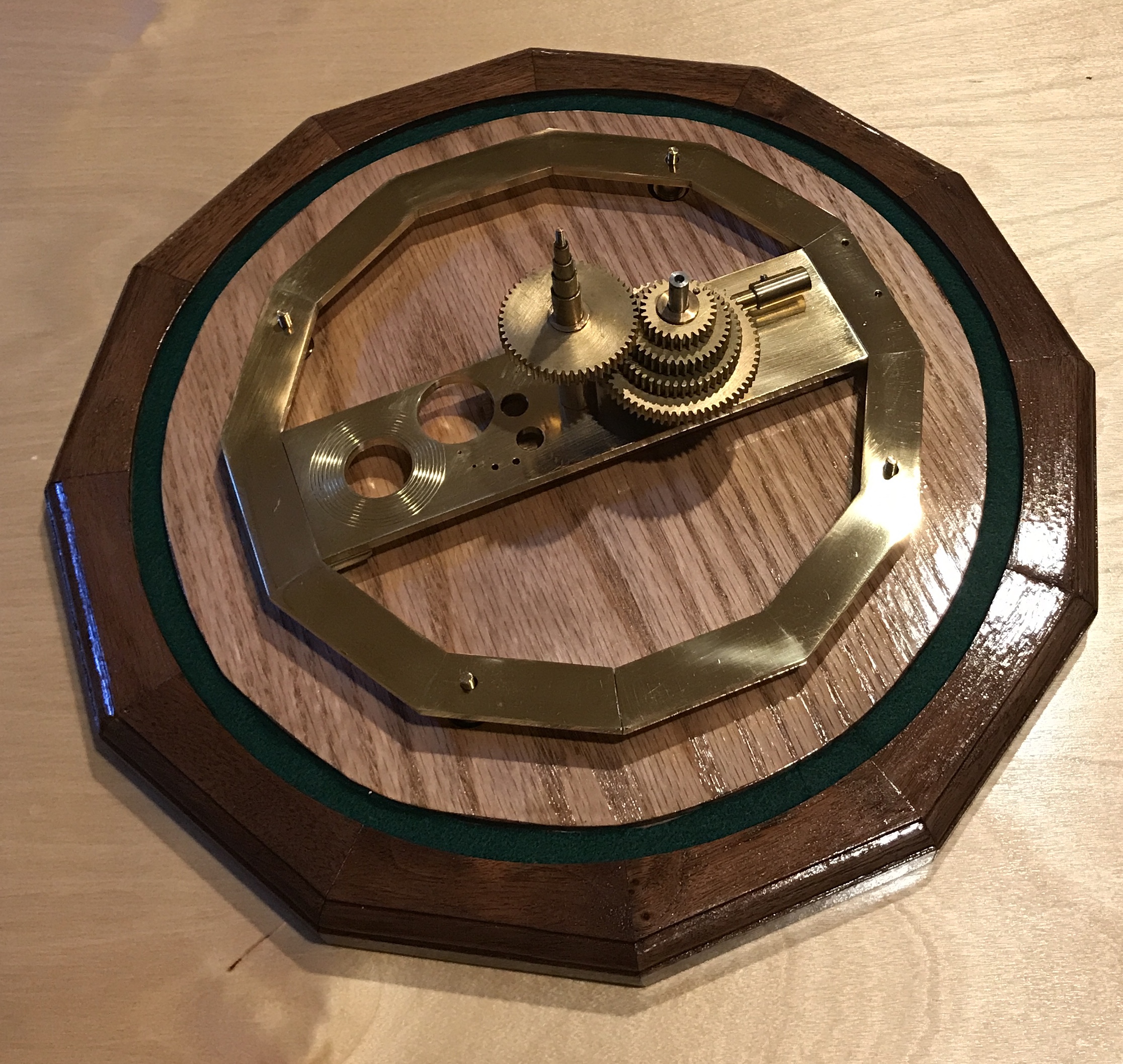
Then the bottom frame was assembled. The bottom support has a number of holes drilled through to show relative planet sizes. The holes sizes represent the planet size, if the sun were the diameter of the orrery as a whole. In the third photo below Saturn is on the far left with its rings sketched out. Jupiter is to Saturn's right. The rest of the planets follow clockwise around an arc: Uranus, Neptune, Earth, Venus, Mars, and finally tiny Mercury. Mercury's size is not accurate as I do not have a drill small enough. The bottom support bracket is screwed to plates, which are then screwed to the bottom of the bottom dodecagon. The dodecagon is set on the feet.
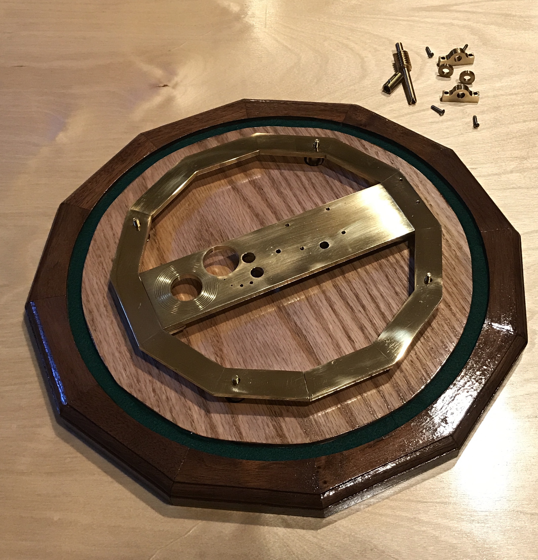
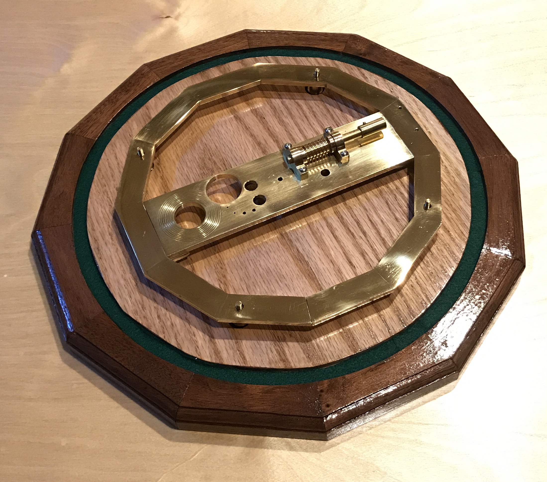
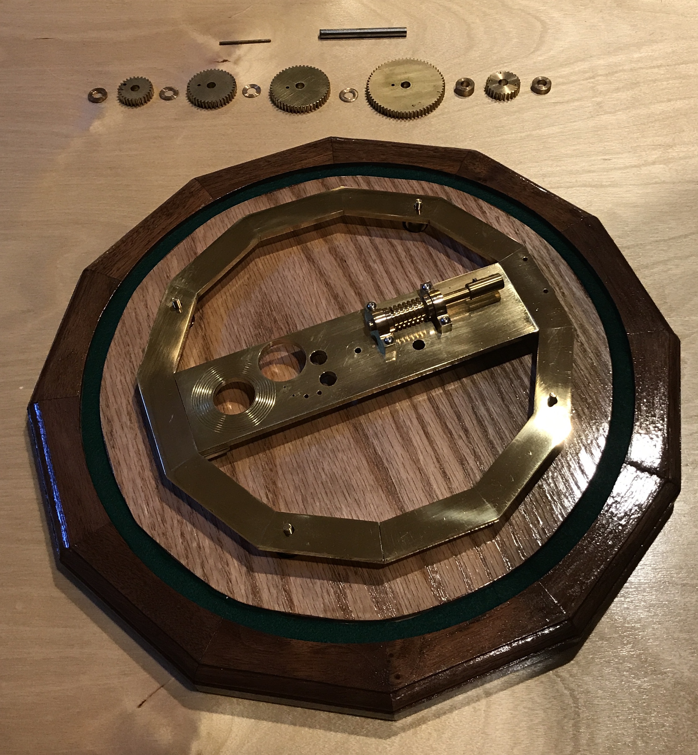
Installing the worm was next. Two thick washers were placed on the worm shaft on either side of the worm. These washers keep the worm from moving sideways along the direction of shaft. The bearings were placed outside these washers and they were screwed to the bottom support bracket. The handle connecting tube was attached to the worm shaft with a set screw. The worm shaft is slotted like a screw, so the mating, screwdriver-like, handle shaft can turn it and be easily removed.
The third bearing block should probably be installed at this point and a straight edge used to align the three bearing blocks. When the gear stacks are installed the bearing blocks may need further adjustment to provide smooth operation.
There are two gear stacks. The first I call the fixed gear stack. This stack is turned by the worm (1/26 of a full revolution or two weeks for each full turn of the worm). It consists of 5 gears. The bottom gear is called the wheel and it mates with the worm. It has 26 teeth. The next gear up, the largest, is one half of the Mercury gear pair. Up next is the fixed gear for Venus. Then come the fixed gears for Earth and Mars. Each gear is separated from the gears on either side by thin brass washers. The gears in the fixed gear stack all need to turn in sync with the worm and wheel. To fix the gears together a second shaft or pin passes through holes in the gears.
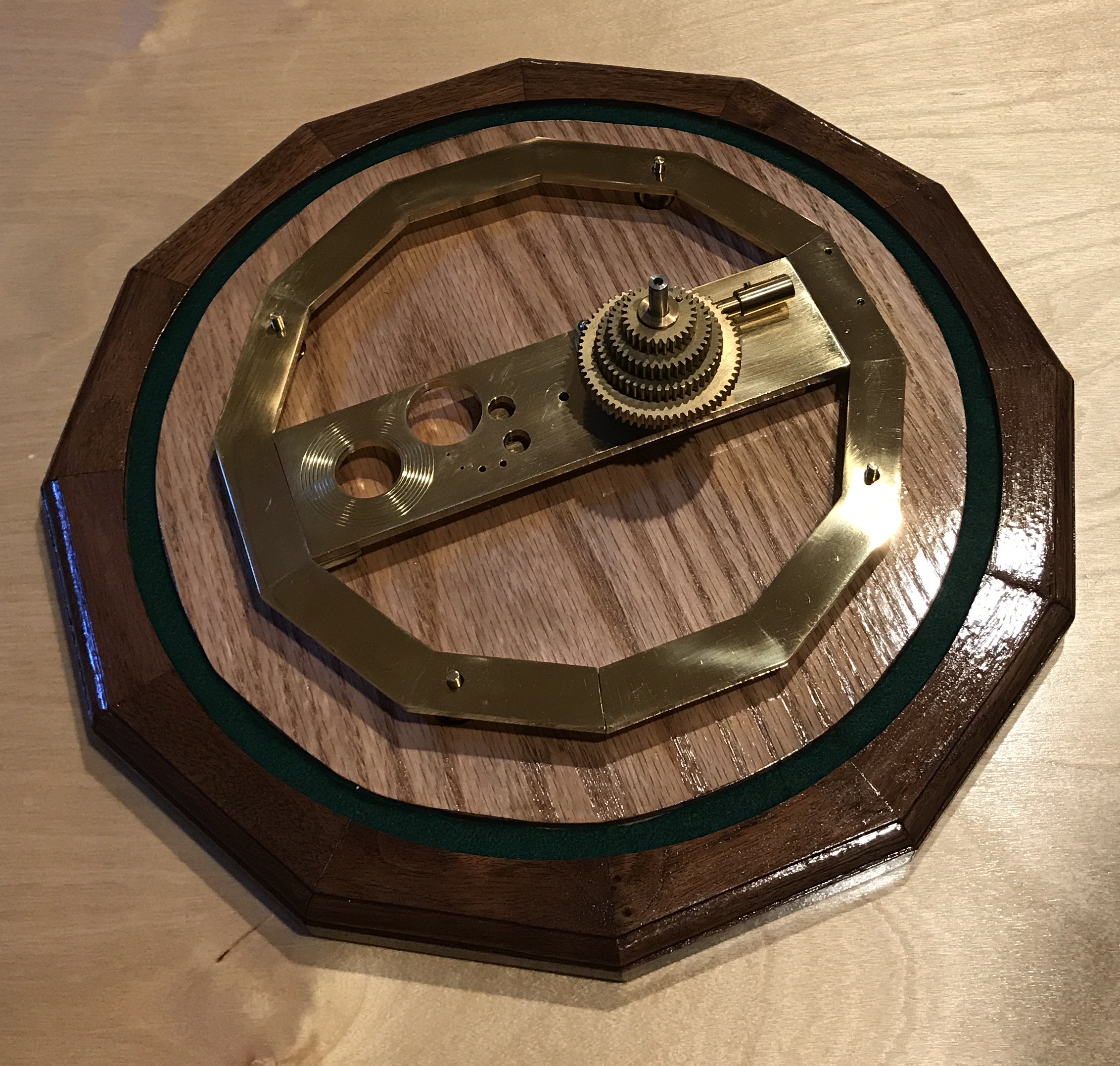
The fixed gear stack meshes with and turns the independent gear stack gears. These gears rotate independently of each other constrained only by their partner in the fixed gear stack. The rotation speed of the independent gears depends on the ratio of teeth between the fixed gear and the independent gear. The Earth gears both have 39 teeth. Twenty-six turns of the worm turns the Earth through one full year. For Mars the fixed gear has 27 teeth and the independent gear has 51 teeth. The ratio of the two gears along with the ratio relative to the number of teeth on the Earth gears sets the speed of Mars relative to Earth's speed around the sun.
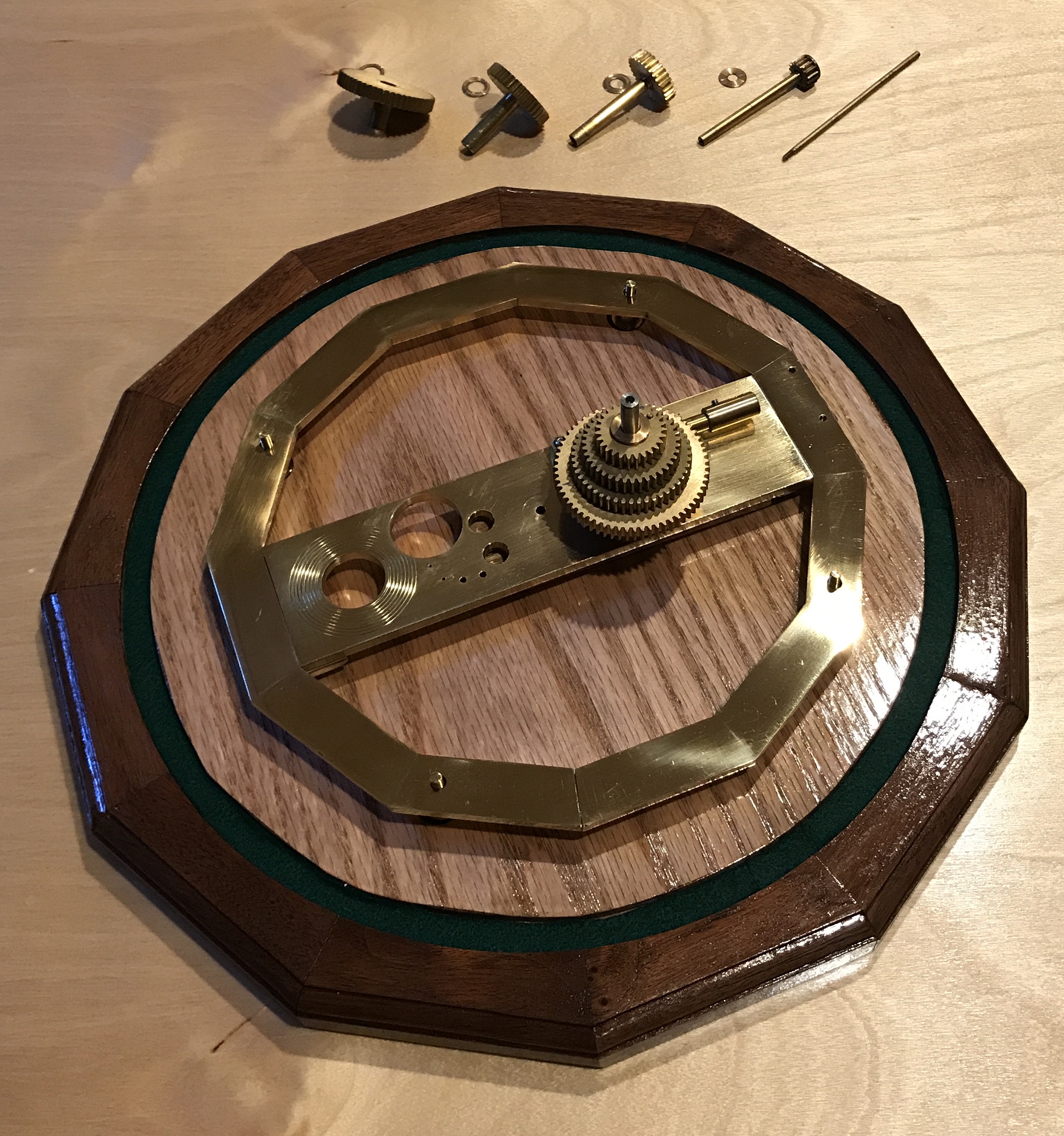
Getting the correct ratios was part of the challenge in selecting the best gear pairs. Another constraint in the gear selection process is that all pairs of gears have to have the same total number of teeth, otherwise they won't mesh (78 was chosen). The third and final constraint was also practical. Cutting gears with fewer than 12 teeth is very difficult and cutting more than 100 teeth is too time consuming, since the teeth are cut one at a time. With all of that considered the gear ratios used here were selected from the 100 or so possibilities explored as they gave the smallest errors: 0.1% for Mars, 0.6% for Venus, 0.7% for Mercury. The spacer shown in the second photo below is to set this gear stack above the height of the worm and wheel.
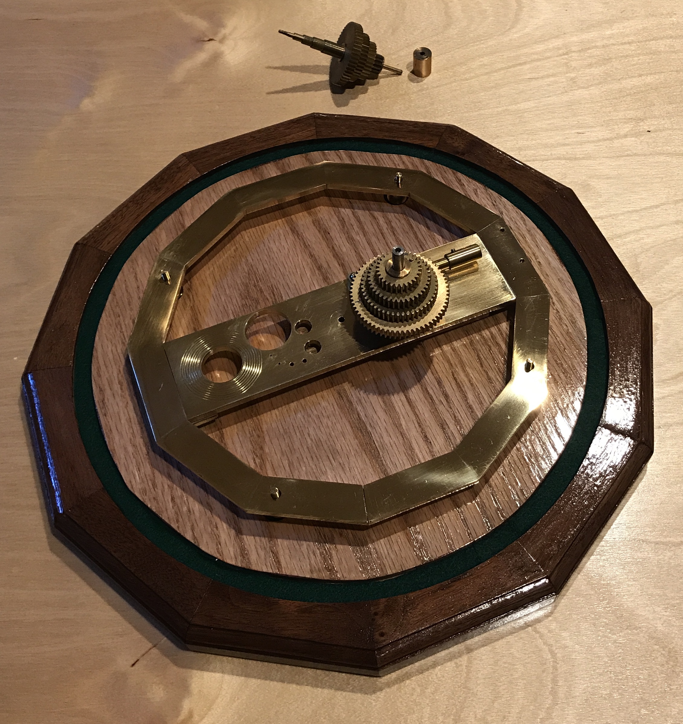
A final aspect of these independent gears worth noting can be seen in the photos. Each gear is mounted (soldered) to a tube. The smallest gear on the right is attached to the narrowest and longest tube. This gear/tube drives Mercury. Its gear sits on the bottom of the stack, but its ring sits the highest in the assembled orrery. So its tube needs to slide through the others. Mars's tube is difficult to see in the shadow. It is the shortest and fattest tube. The Mars gear sits at the top of the stack and its ring is on the bottom of the four rings. So it has the shortest tube. Its tube is the widest because the other four tubes must slide through it.
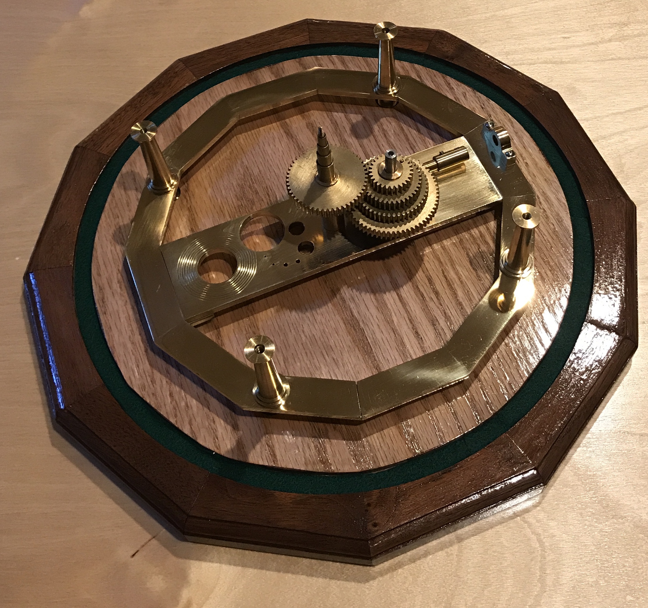
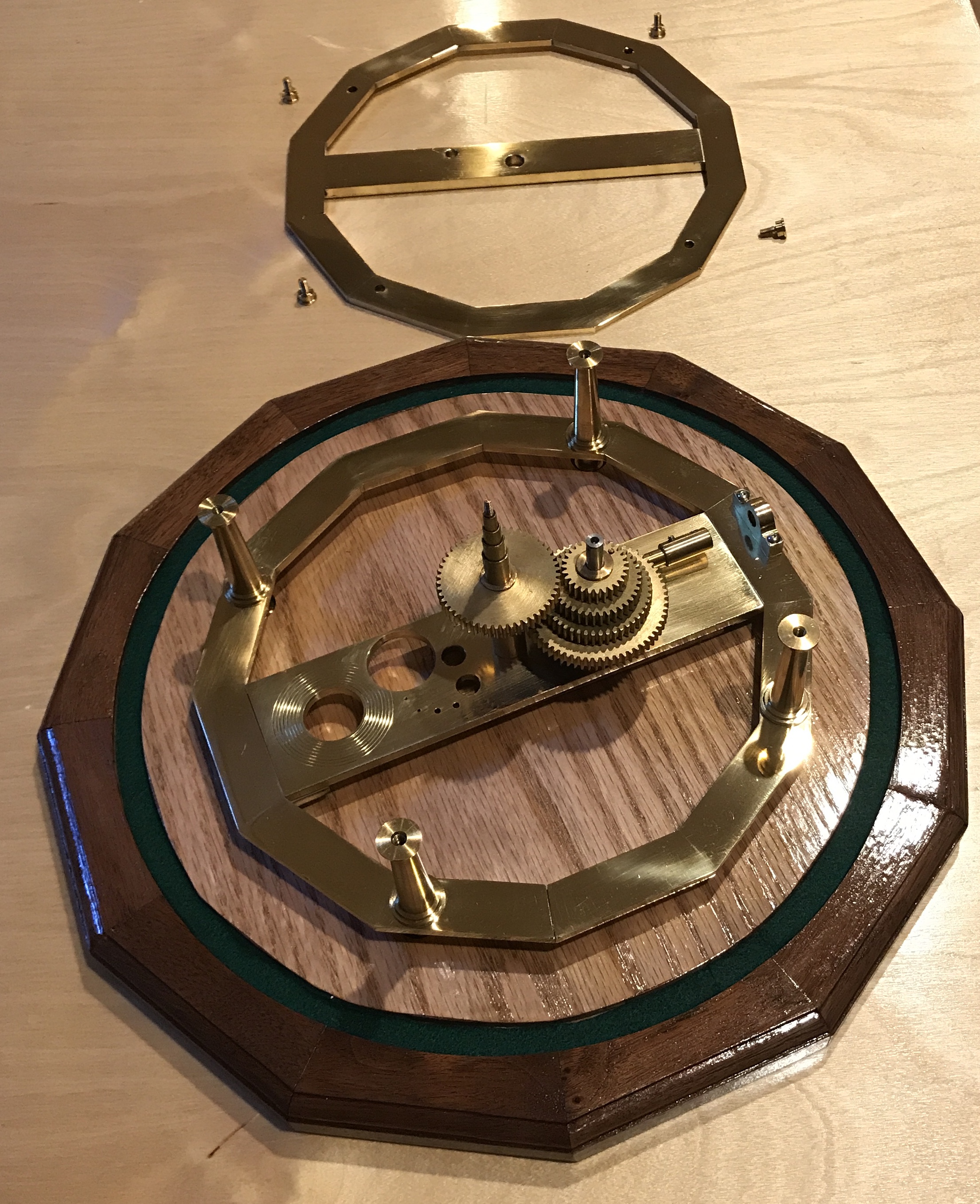
The columns and the handle bearing were added to the assembly next. The columns are screwed to the feet and sit on top of the bottom dodecagon. The bearing for the handle shaft is screwed to the bottom dodecagon. (Interesting how the reflected light makes the bearing look blue in the photos.)
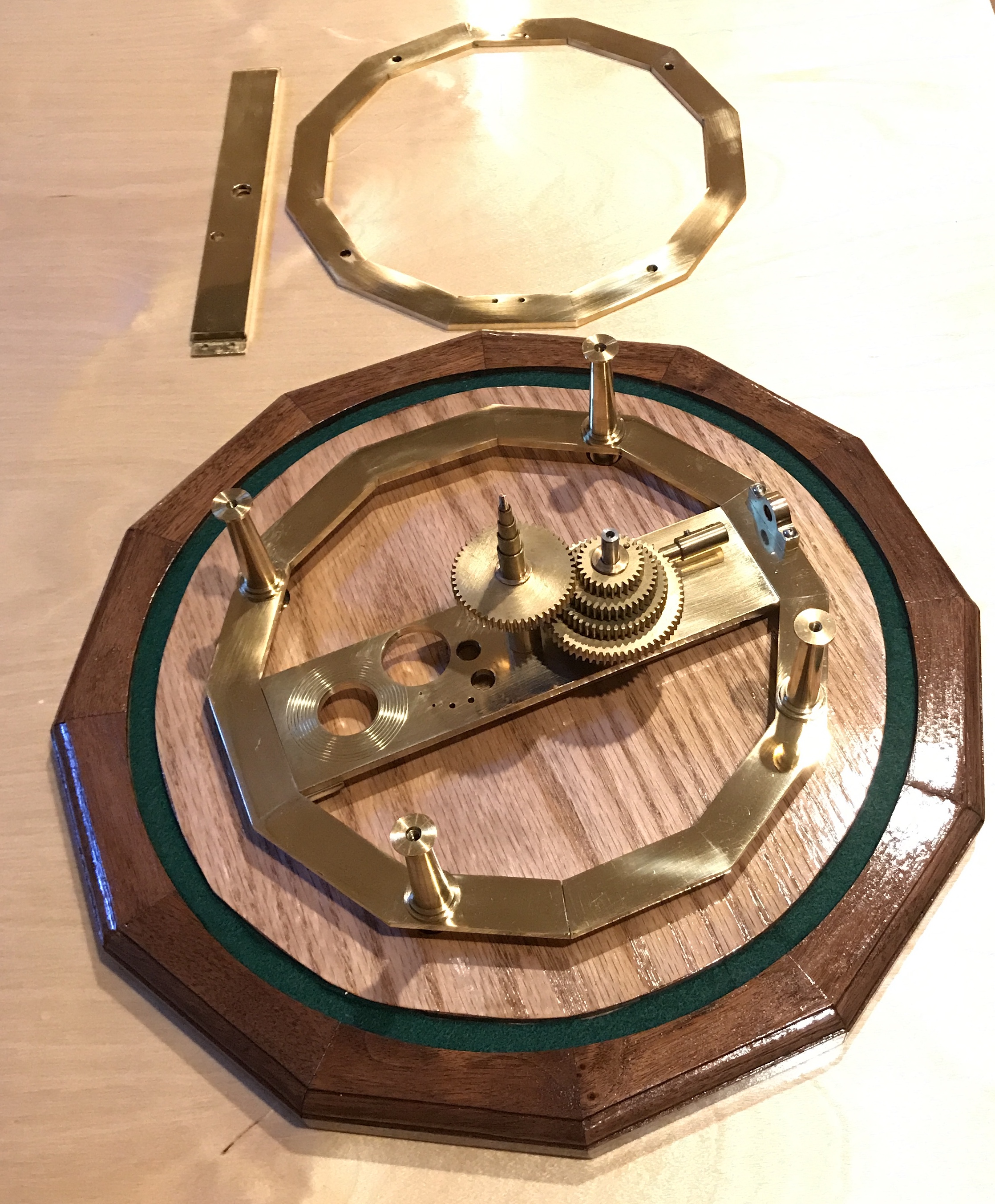
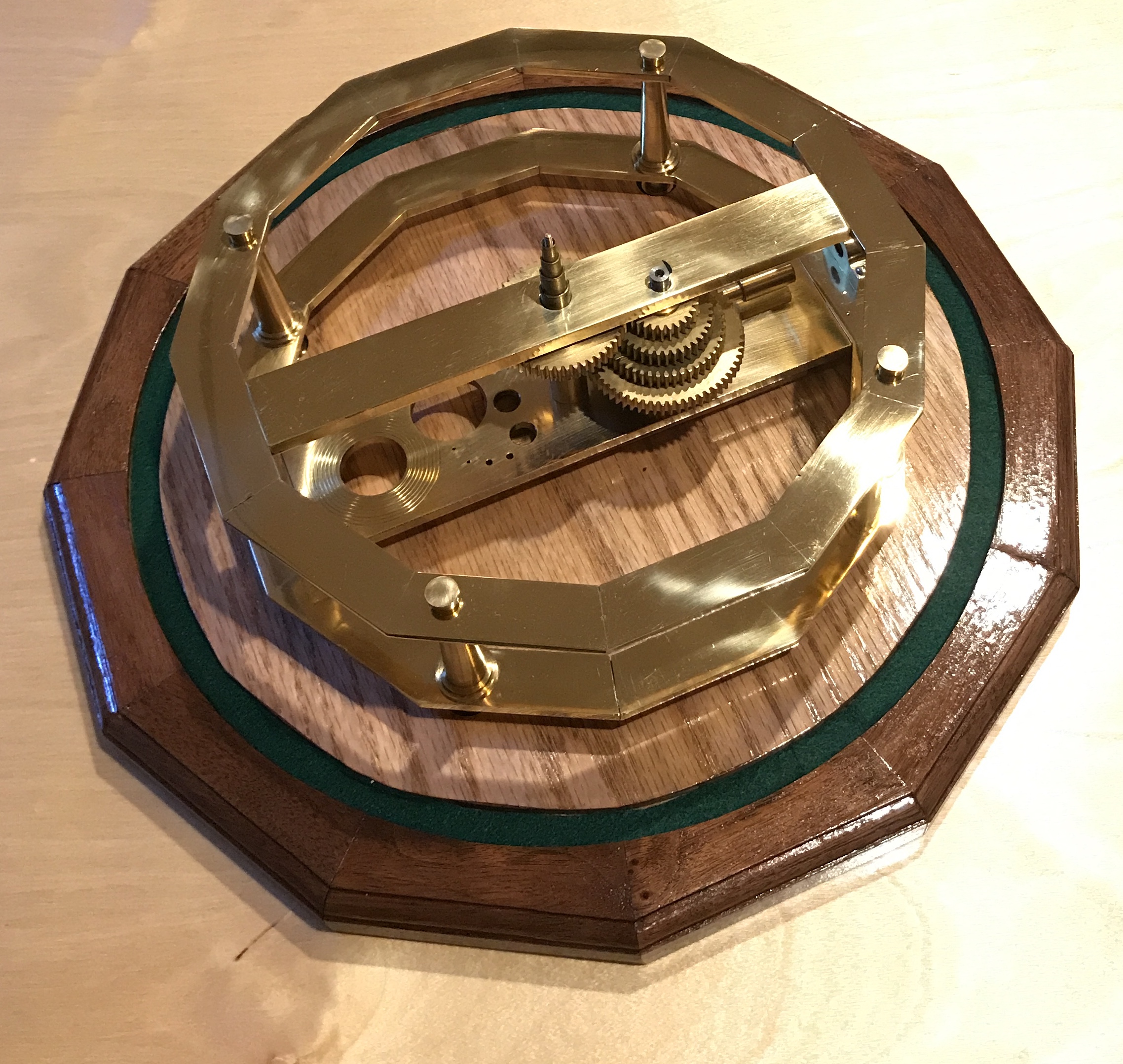
The top frame is added next. It holds the tops of the two gear stacks in a fixed position relative to one another. It consists of two parts, the upper dodecagon and the top frame support bracket. This latter is screwed to the dodecagon and the whole is set on the columns. The top dodecagon is then screwed to the columns with the column caps seen in photo 2.
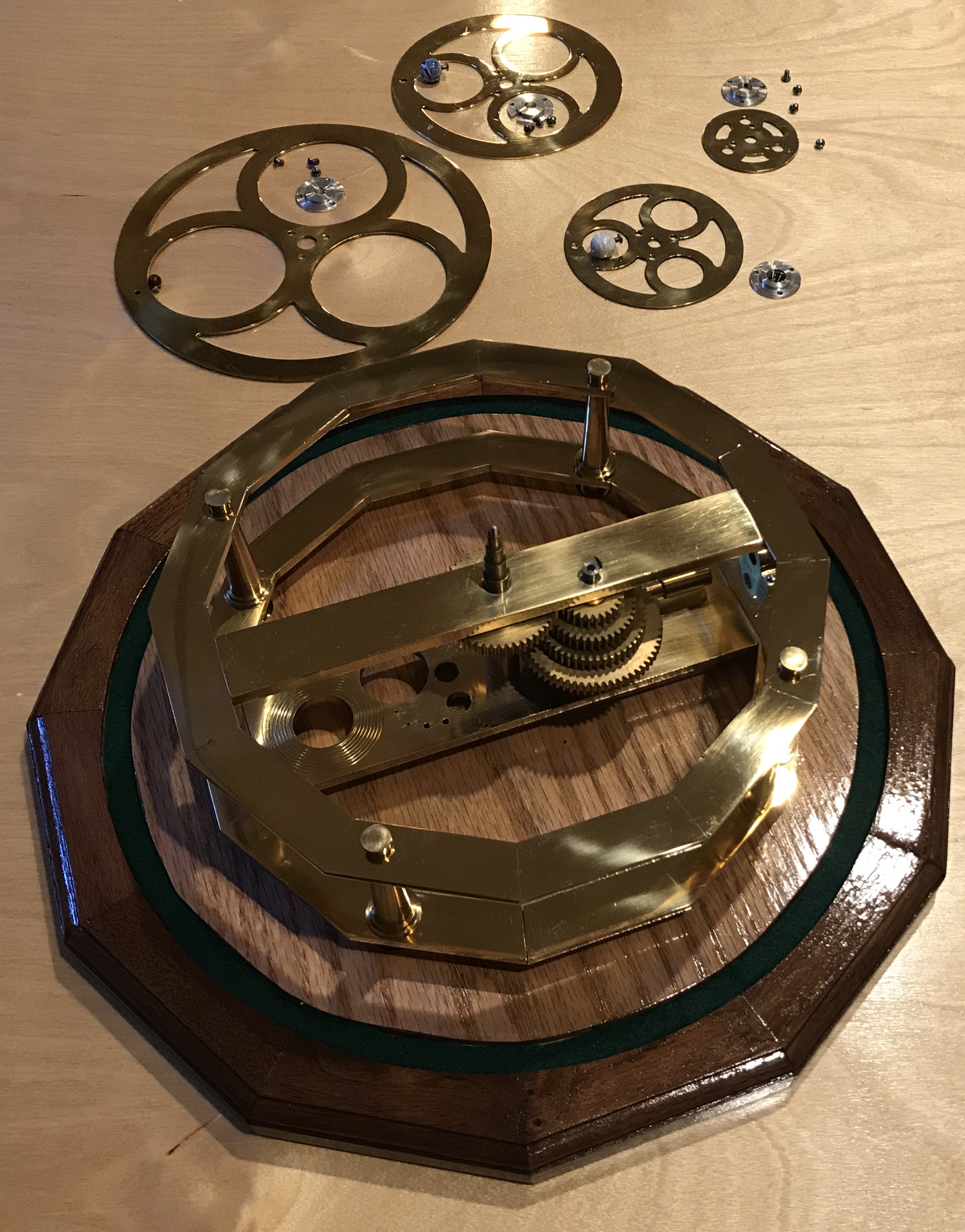
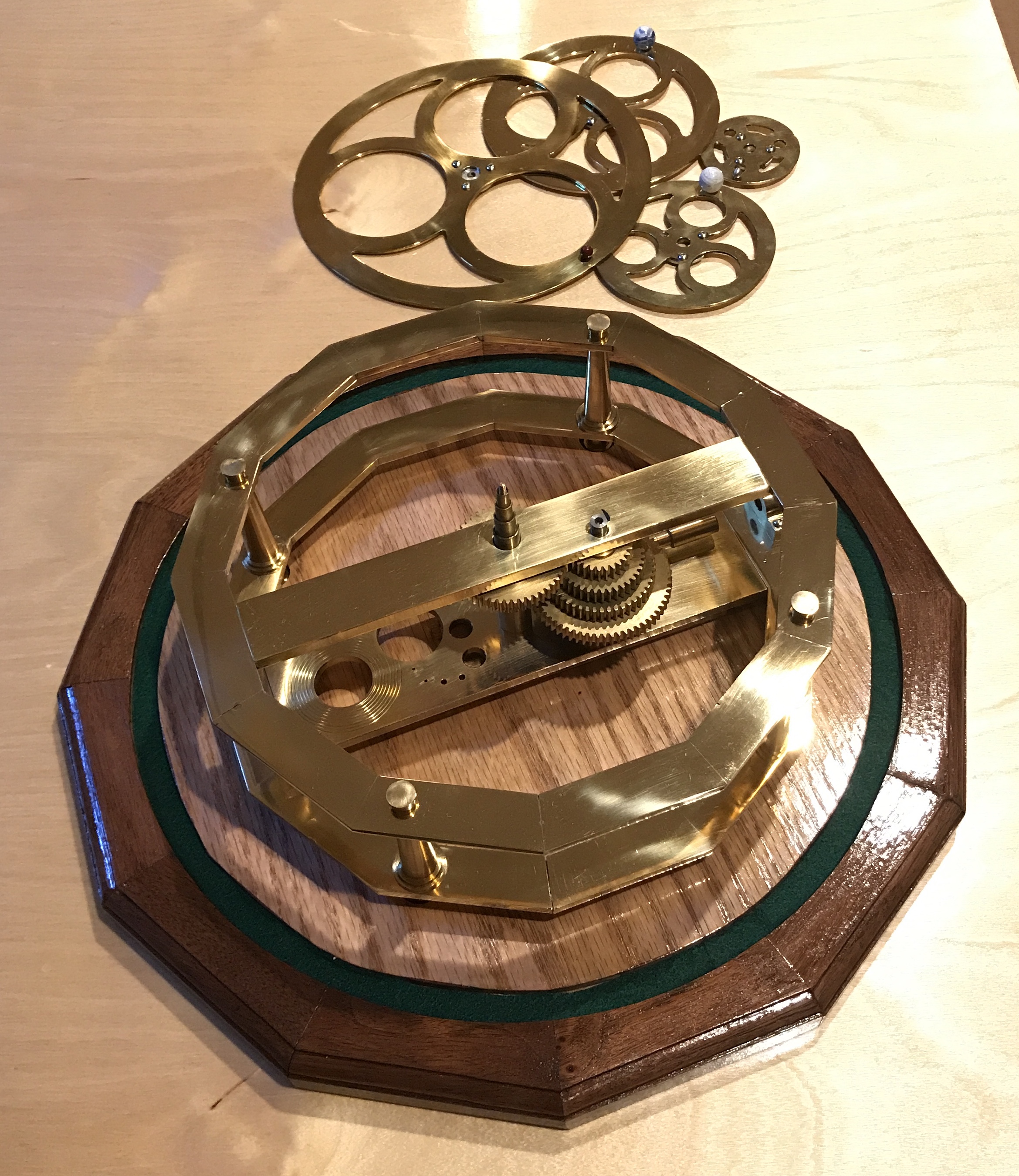
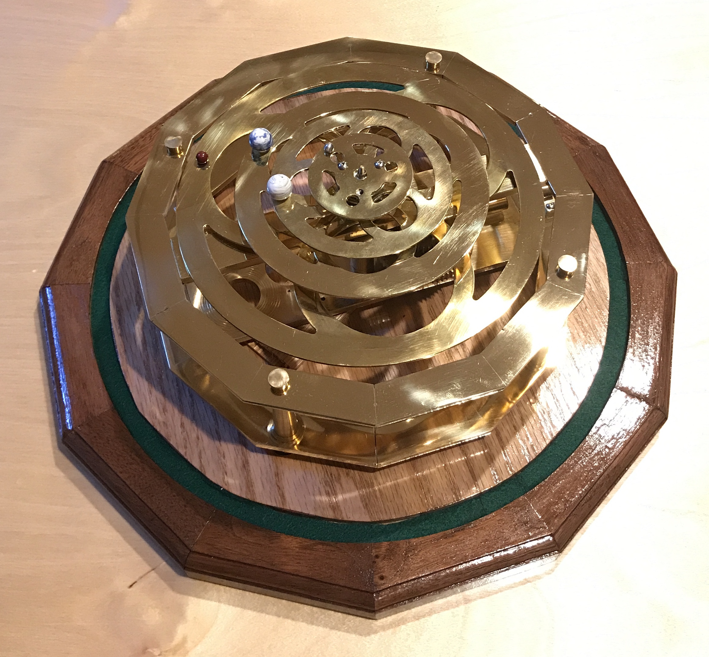
The planet rings are added next so the assembly finally looks like an orrery. The four planet rings each consist of three parts: the ring, the planet and the attaching collar. The aluminum collars attach to the back of the ring with three screws. A set screw mounted in the collar afixes the collar to the corresponding planet tube. The planets are small metal balls. Two were made from brass, one from aluminum, and one from steel. Three were then painted, Mars, Earth and Venus. Mercury was left as a polished steel ball. The planets are attached to the rings with a screw. For this assembly the planet positions do not reflect their current location in their orbits.
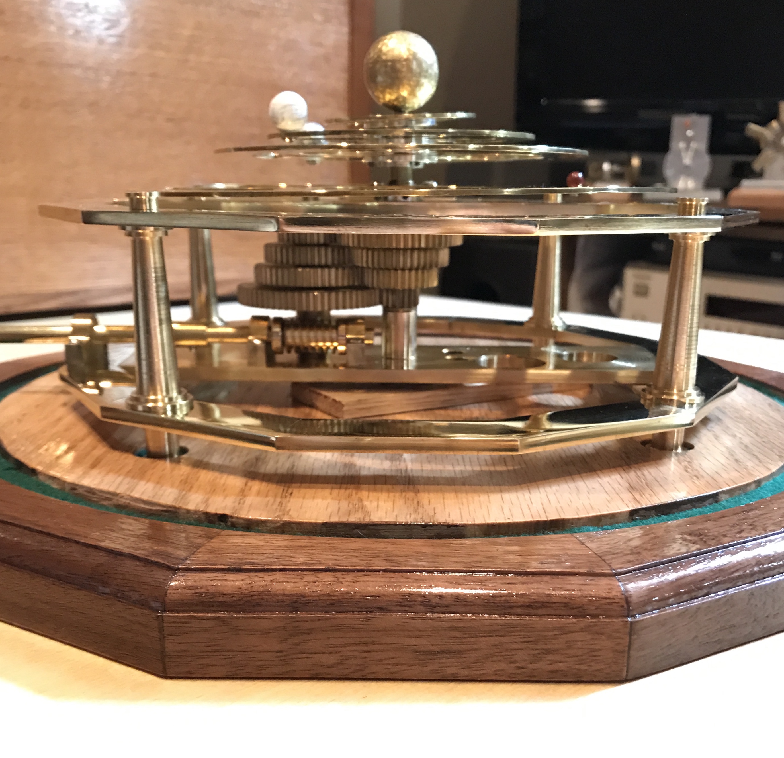
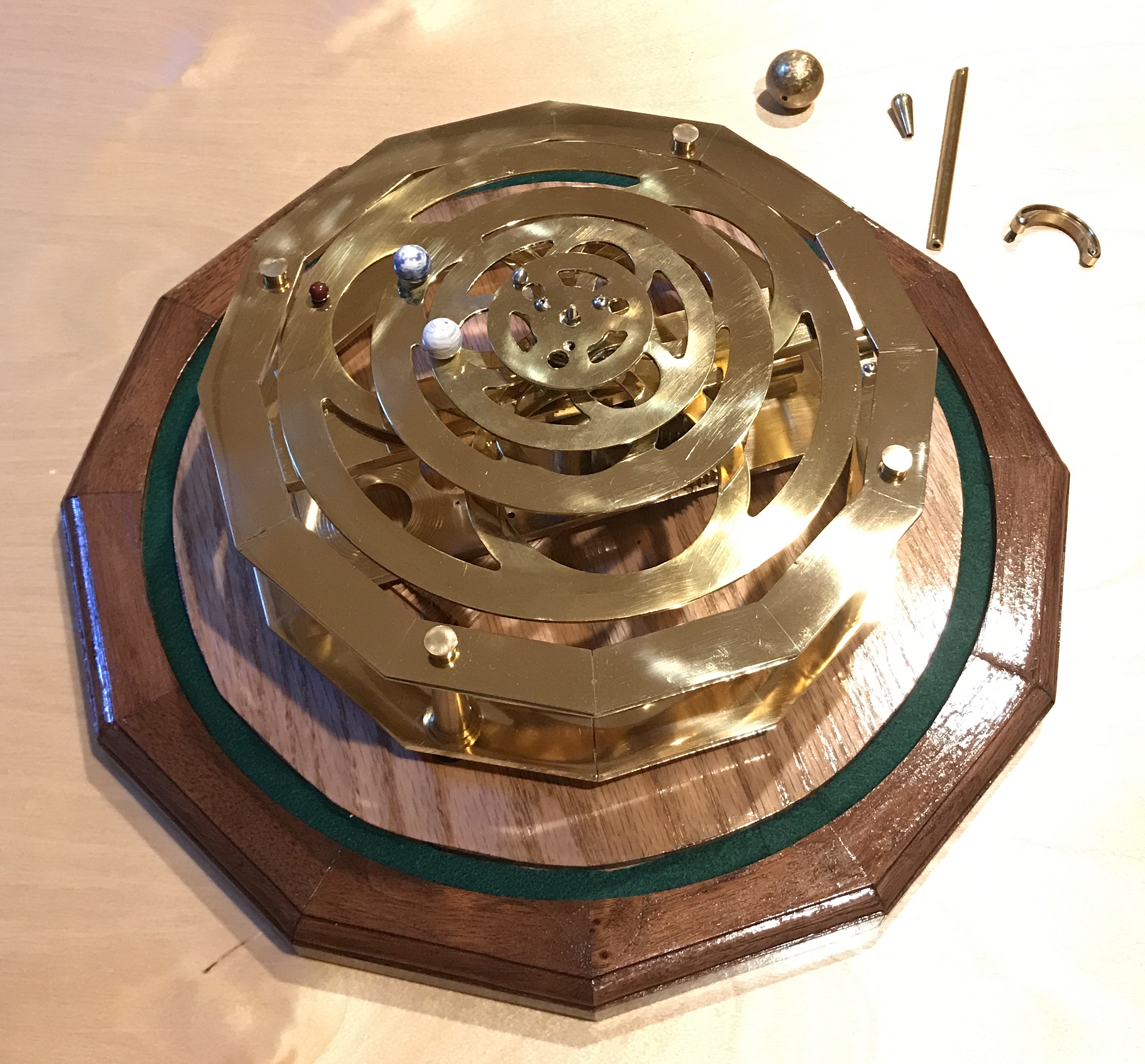
A few finishing touches completed the assembly. The sun is just a brass ball sanded a bit to look interesting. It is screwed to a shaft that runs up through the center of the Mercury tube. Both shafts eventually need to be permanently attached to the bottom support frame. (An alternative to permanent attachment is affixing a small plate under the two holes for the gear shafts.) At this time the shaft rests on a block of wood hidden under the frame. The handle consists of three parts: the shaft with the screwdriver-like end, the curved connector and the knob. These three parts are assembled with two screws. The shaft slides in through the handle bearing and slots into the worm shaft.
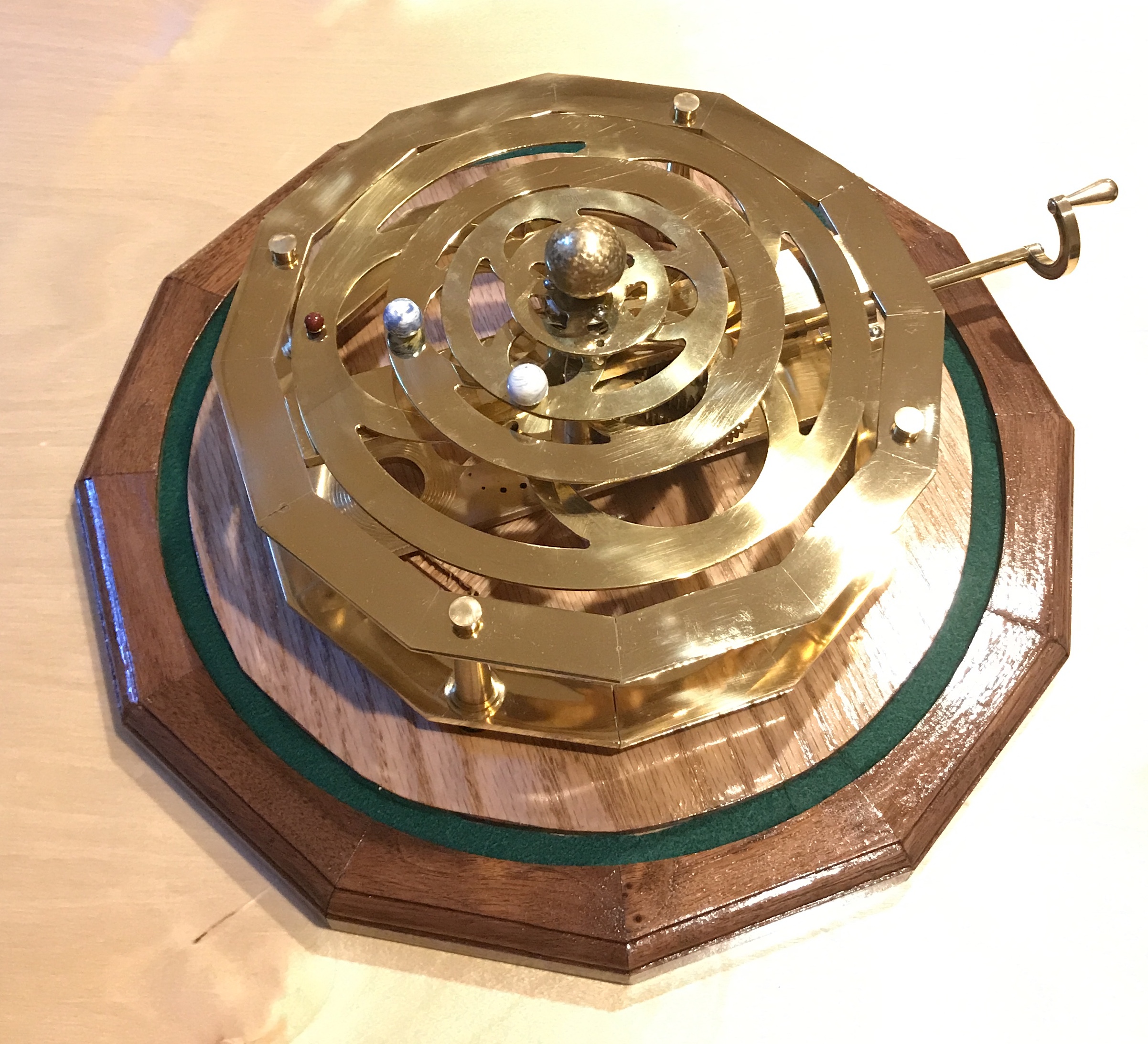
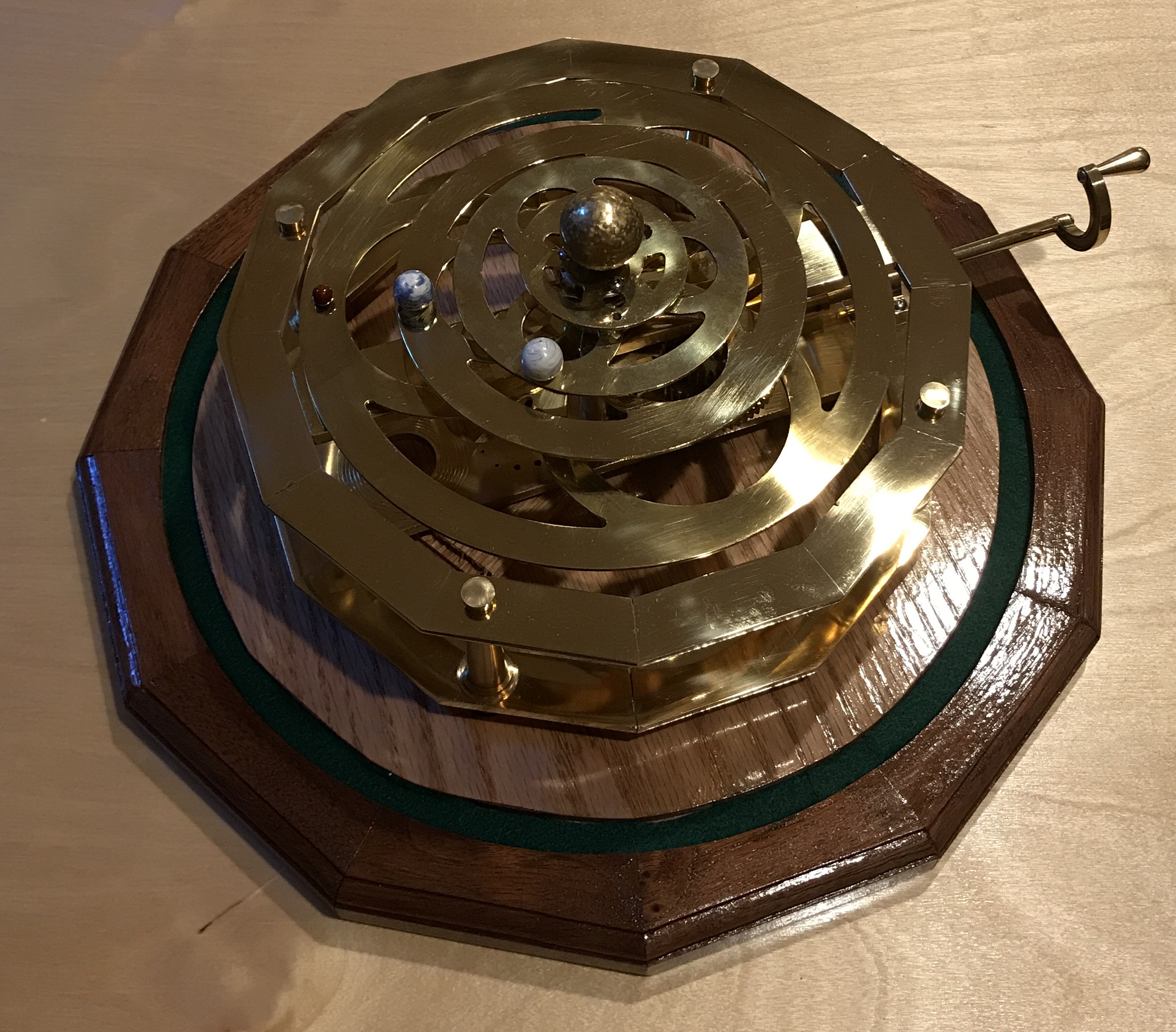
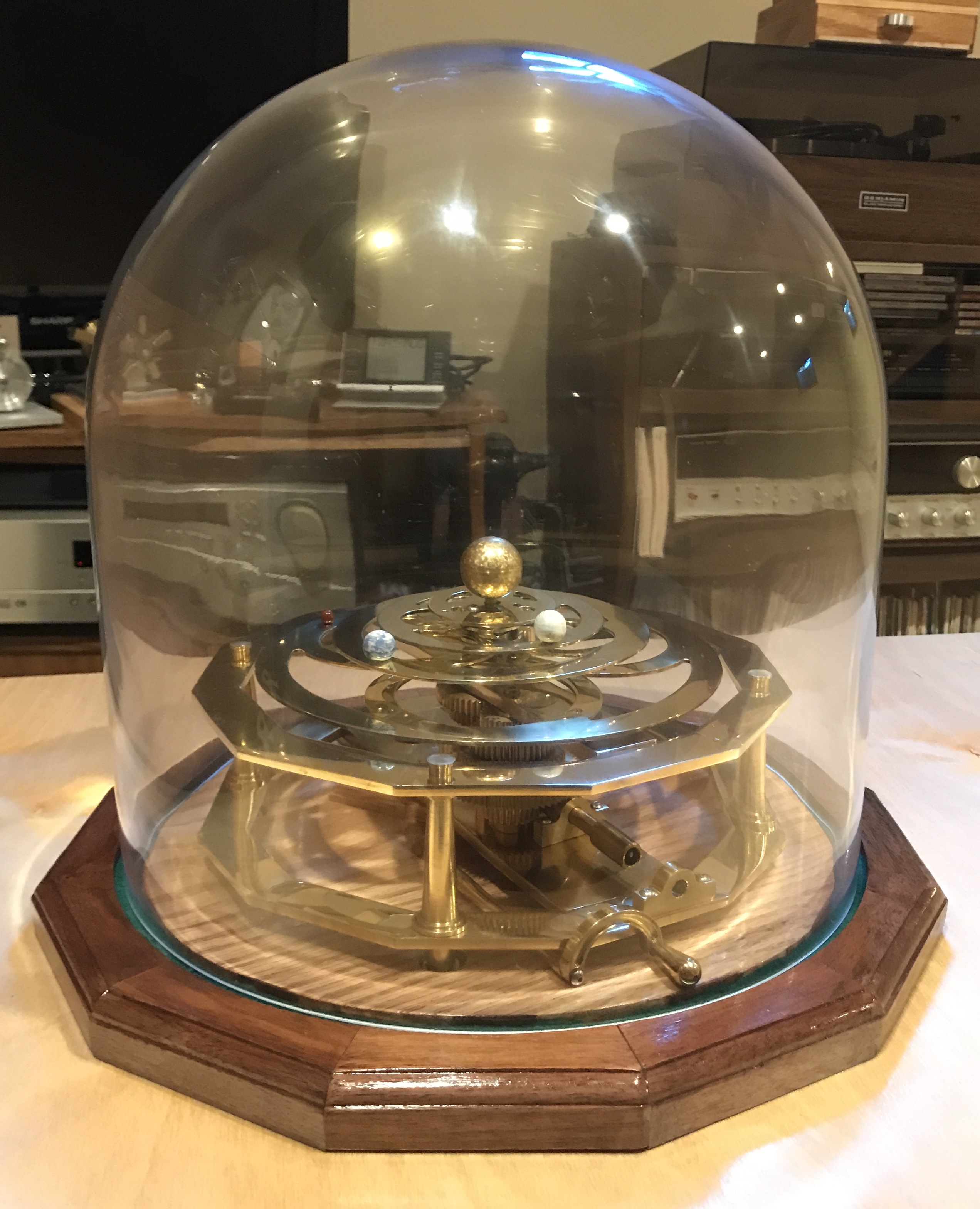
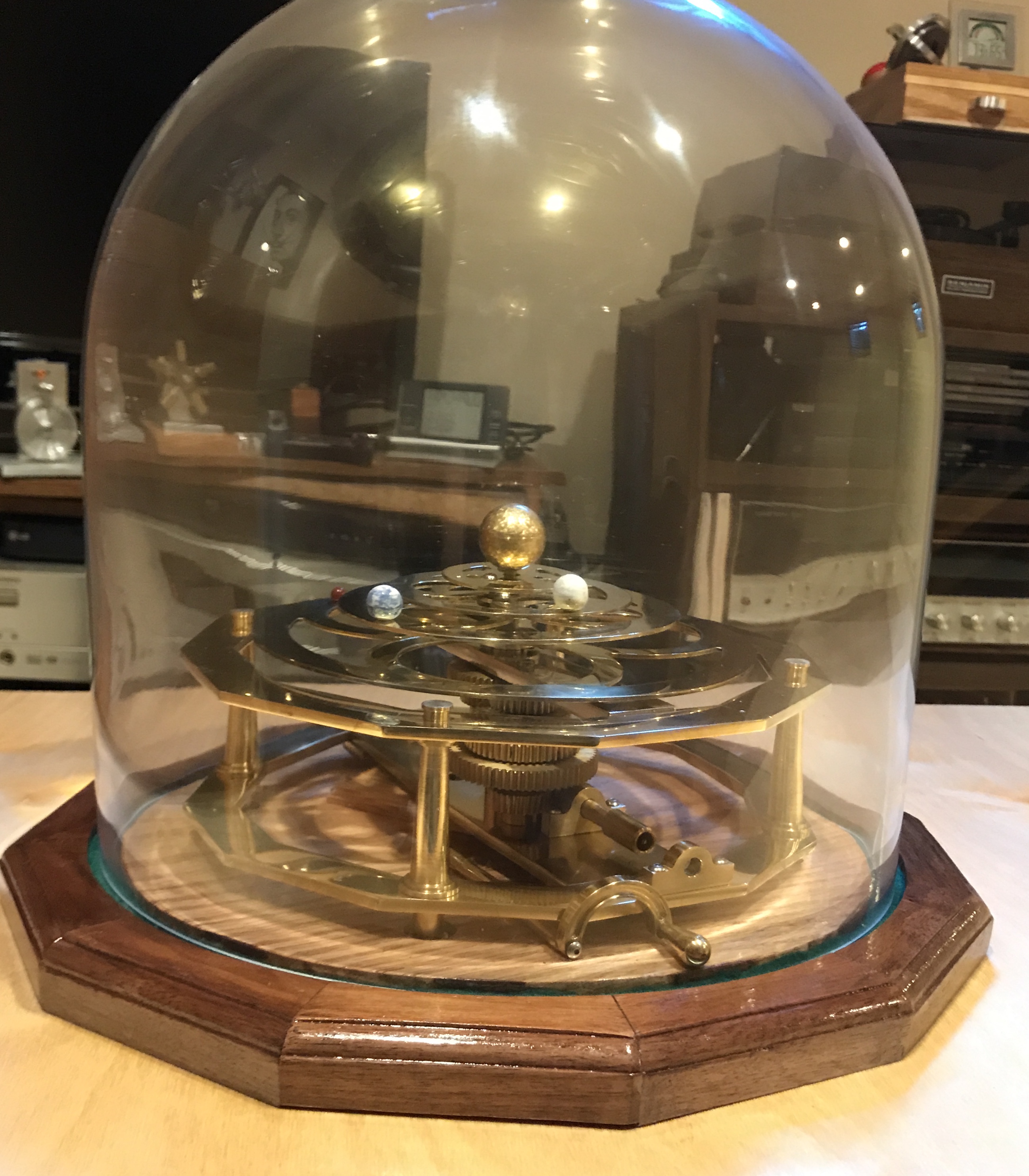
The final photos are superflous. There is an additional shot of the assembled orrery. There are also two photos of the orrery under its glass dome. (The dome needs to be cleaned!) Note that the handle is removable so the dome can fit over the orrery. The handle is stored under the bottom frame.
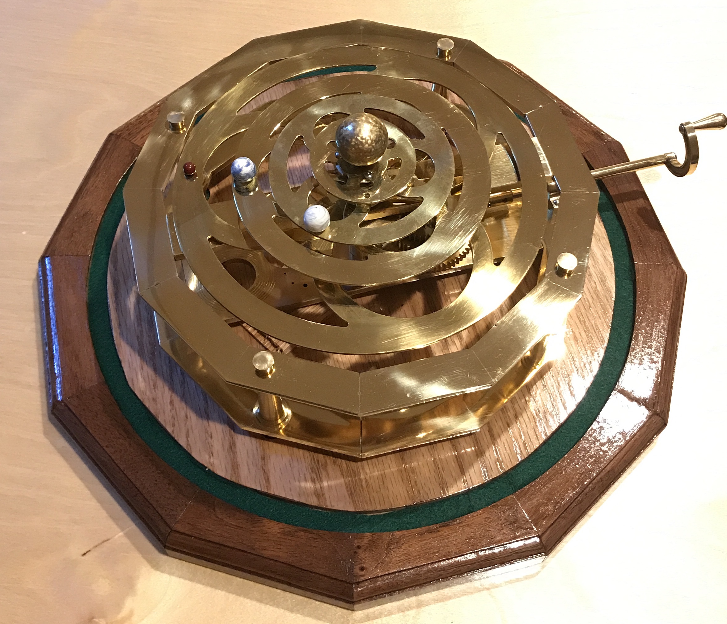
A final shot highlights the gears beneath the planet rings. Note that the Mars ring is attached too low.